The goal of this experiment is to understand, and build an eddy current ring launcher. This video shows shows some aluminium can destruction and the launching of an aluminium ring using eddy currents. Besides that it looks cool, I want to understand the underlying process, so that it is also educational in the theoretical sense, instead of “just building” something.
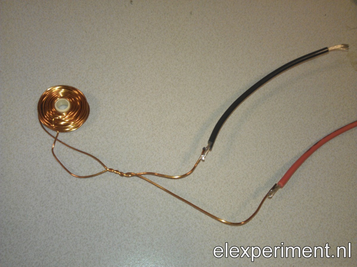
A quick test with a small coil from 0.8mm magnet wire that I had lying around, combined with a capacitor of 22000μF charged up to 40V, showed that the concept worked. The coil had dimensions of about 5x15x5mm (inner dia., outer dia., height). This launched a small piece of aluminium to a few millimeters. Nothing spectacular, but interesting enough for further investigations.
So, knowing that the concept works, it is time to involve some theory, with the goal of understanding and optimising the system. The first tool in doing so is the very nice FEMM software package. This allows us to do a finite element method analysis of the system, with which hopefully a step response can be modelled.
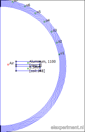
Since I like to automate things, the analysis is script based in Matlab. The script does the following: first, it opens FEMM, and initialises an axisymmetric problem. Next, it draws coil with a certain current, wire diameter, and number of windings. The aluminium ring is added at a certain distance. Finally, an asymptotic boundary condition is added to simulate an open boundary. This looks as follows, in the preprocessor (left) and postprocessor (right):

So, there we have a setup for the problem. But what should be done next? To simulate the movement of a ring, the problem needs te be evaluated at several heights for the ring. Also, FEMM can provide results for a certain frequency, but the step response is in the time domain. A suggestion found in the FEMM archive suggests obtaining the frequency response, after which a transfer function can be fitted. This transfer function can be used to obtain a step response.
I tried this approach, but for this problem it isn’t very straightforward to get a step response. First of all, the magnetic materials are linear, but a lot of other properties are not. For example, the current induced in the ring changes (non-linear) with distance. Also, the force exterted on the ring increases with the squared of current. Third, FEMM works with currents, thus the force in the ring is computed as a function of current in the coil. In the real world, a capacitor is probably used, thereby supplying a voltage, which in practice is also not constant.
Because of al these complications, I thought it to be nice to model the system. After all, it is basically a transformer. At least I hope so, as it allows to model the system completely. This “transformer” has a low coupling factor, very different inductances, and the secondary (the ring) is shorted. The figure below displays the transformer, with primary inductance  and resistance
  , coupling factor
  , and secondary inductance
  and resistance
  .
.

This can be also be represented by an equivalent circuit with a mutual inductance  :
:

The idea is now to derive transfer functions for this circuit with coupled inductors. The circuit has three branches
(1) 
As stated earlier, FEMM works with currents, not voltages. The force exerted on the ring is probably proportional to its current (Lorentz force), and this current can be evauluated in FEMM. It is thus interesting to obtain the transfer function from coil current  to ring current
(2) 
For a coil with dimensions 10x25x3mm and a current of 1A, and a ring with similar dimensions, the induced current in and force exterted on the ring can be computed. A gap height of 1mm is used. Mutual inductance  can be obtained from FEMM according to
(3) 
With  the number of windings of the ring, thus one,
  the coil current,
  the surface area of the ring, and the integral represents the integration of the magnetic vector potential from the coil integrated over the area of the ring.
The ring inductance and resistance can be obtained from FEMM by adding a circuit property to the ring. This gives  ,
,  and
and  . These values are quite low, but that is probably because of the ring having only one winding.
For a current of 1A in the coil, the current in the ring is evaluated at a range of frequencies. The figure below shows a plot containing both the values from the model, as the FEMM values.
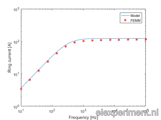
Well, that is not too bad! A slight error can be seen between model and FEMM results, but for a first try it looks good enough to me.
That’s it for this (quite long) post. Next steps in this experiment are to include the primary circuit, to experiment with multiple gap heights, etc.
?