For today’s experiment, the goal was to make a simple buck converter, based on an XL4005 I had lying around. Since I don’t have experience with building an actual switching voltage regulator, this is a nice and educational experiment.
The circuit is basically the application example of the XL4005 datasheet:

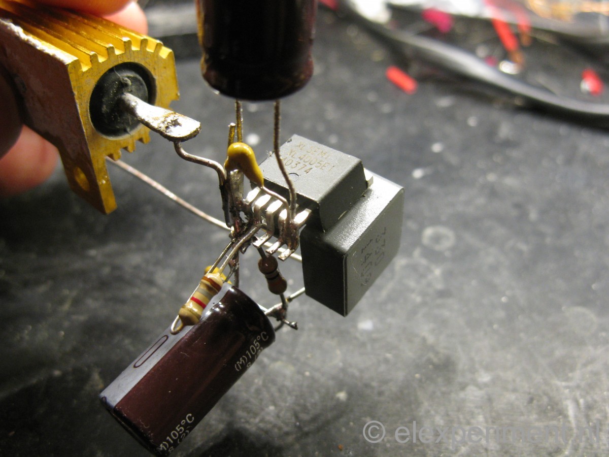
Operating frequency is about 300 kHz according to the datasheet. The reference voltage for the feedback (FB) pin is 0.8V, thus resistors R2 and R3 result in an output voltage of 0.8 * (1 + R3/R2) = 5.24V. Capacitor and inductor values are obtained from the default values specified in the datasheet. The diode is recovered from the PCB of an old hard drive. It was part of some switching converter, and looked beefy enough.
Soldering a PCB consumes quite some time, so it’s time to get creative. Also, this keeps component leads to a minimal length :).
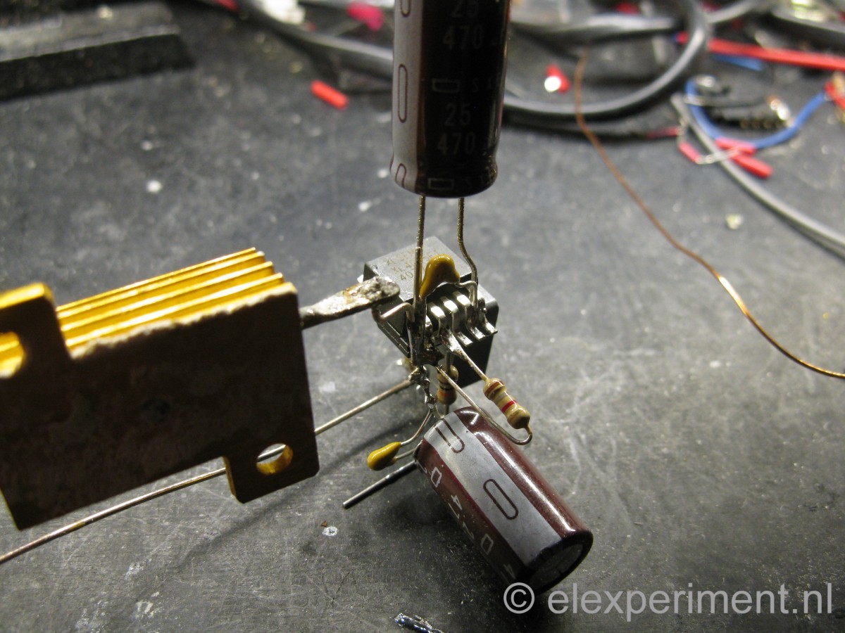
The load resistor has a value of 1.8Ω, thus at an output voltage of 5.24V that results in a current close to 3A. In practice the buck converter had an output voltage of 5.3V, thus dissipating 5.3^2/1.8 = 15.6W in the resistor, which gets fairly hot after some time. All of the other components stay completely cool. Input power at an input voltage of 20V was measured to be 18.5W. Efficiency is thus around 85%, not bad at all for a first switching regulator :).
With a 470uF output capacitor, output voltage ripple is as follows:
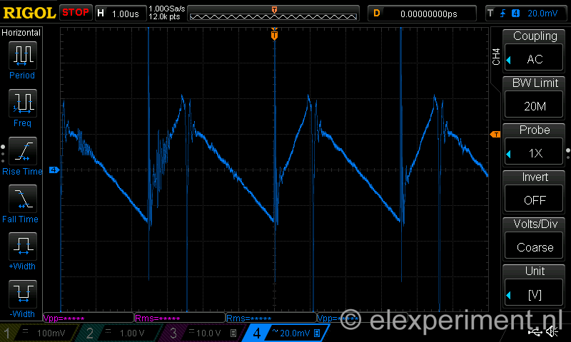
Thus, approximately 60mV ripple. Not that bad, except from the two large voltage spikes (when the FET switches on/off).
So, summarising: a nice experiment, and apparently making a switching buck regulator isn’t that hard nowadays.
How about with LM2596 ..?