Often, technical projects are about solving problems and improving things. Sometimes, it’s nice to just make something because it looks nice. In this case, it’s about making a dual laser current source, in a nice looking way. Who needs a PCB, when you have some imagination :).
To be honest this creation is part of a bigger project, so the reason to make is not solely to produce art. For another project, which I hope to document here in the future, I need to have a constant voltage generated by a photodiode (and trans-impedance amplifier), when lit by a laser beam. As both the laser and photodiode have variation in efficiency (besides alignment variations), the laser current needs to be adjusted.
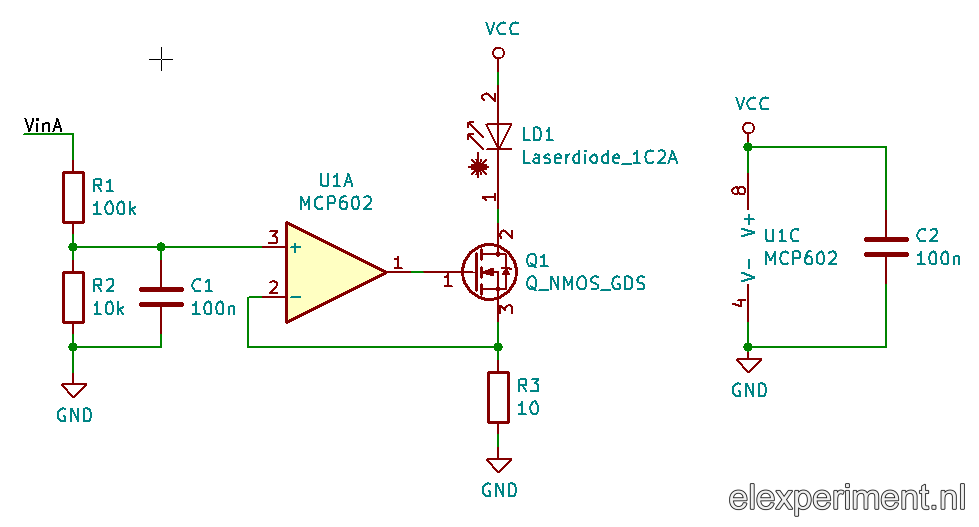
The circuit itself is quite simple: an opamp, regulating its output voltage such that the voltages at the inverting and non-inverting inputs are (virtually) equal. Hence, the voltage drop across the sense resistor R3 will be equal to the reference voltage, created by the voltage divider R1 and R2. Parallel to R2, a 100nF capacitor is placed, making a low pass filter with a cut-off frequency of about 150 Hz. This allows to drive the input with a PWM signal, which can be generated with any simple microcontroller. A relatively low impedance sense resistor is used (which thus requires a voltage divider at the input), such that most of the voltage is dissipated in Q1; this provides more room for a variating voltage across the laser diode. Of course, the circuit depicted below is duplicated, to have two current sources.
After fiddling around with some SMD components, it looks as follows:

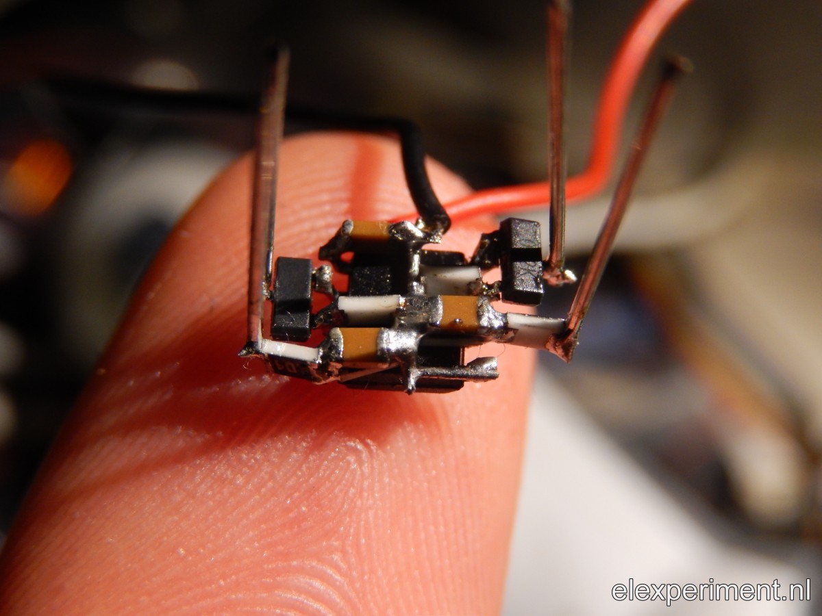
A tad compact, as you can see! I’m happy with the result :).
Do I understand correctly that the FET is used in its lineair region? What type/partnumber is it? Would this work with just any (switching) NMOS?
Yes, the FET is used in the linear region. I forgot most of the details (sorry about that), but for this application probably any nMOS details will suffice.