Making a present can be quite complicated. Mostly it’s not the making that is hard; getting the idea is the crucial step. Once the idea is in, the rest follows (although it can still cost a lot of time).
So, after months of tinkering and thinking, no idea that was good enough came across my mind (might also depend on my definition of good). Finally, an idea that I had seen some time ago popped up: a magnetic table lamp: http://www.instructables.com/id/Magnetic-table-lamp/. The only issue: I had just 10 days left to design and build the whole lamp.
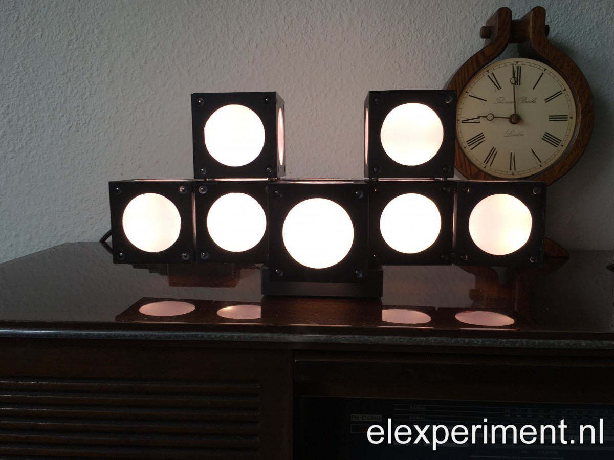
The concept of the lamp is to have a number of separate cubes, that can be combined in any possible shape, resulting in a fully customisable, nice looking lamp. The cubes are connected by means of permanent magnets. Simultaneously, these magnets (and their conductive coatings) provide electrical connections.
So, within 10 days we should have a complete product, with limited tools available. With the 3D printer being the only tool that I have available (on short notice), it is the perfect choice here. The next step is to work out the concept, or at least optimise it, as the concept is taken from somewhere else. This means, thinking of improvements, such that the whole system can be designed and built within 10 days.
The first of those is to use 10mm steel ball bearing balls, to which the magnets connect.
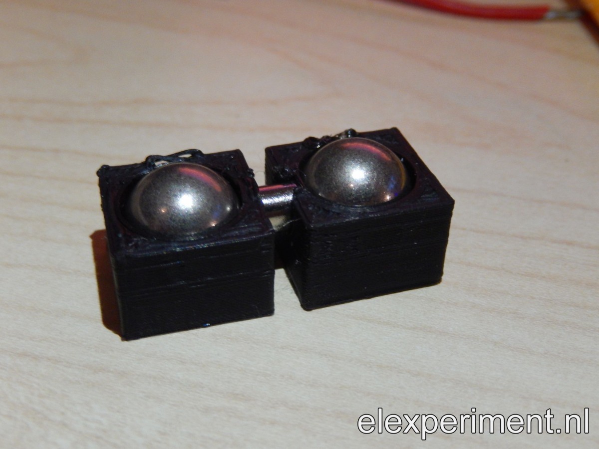
Cube connnection concept
Using a combination of steel balls and magnets has several advantages:
- Instead of 6×4 magnets per cube from the original design, now magnets need to be placed only where cubes are connected. This also provides a “cleaner” design. Magnets are relatively expensive, so it reduces cost as well.
- With pairs of permanent magnets, special attention needs to be paid to polarity (north/south poles). By using ferromagnetic steel balls, this problem is solved.
- You can solder on these ball bearing balls, to my surprise! This allows to directly add wiring, and prevents the use of (expensive) conductive glue.
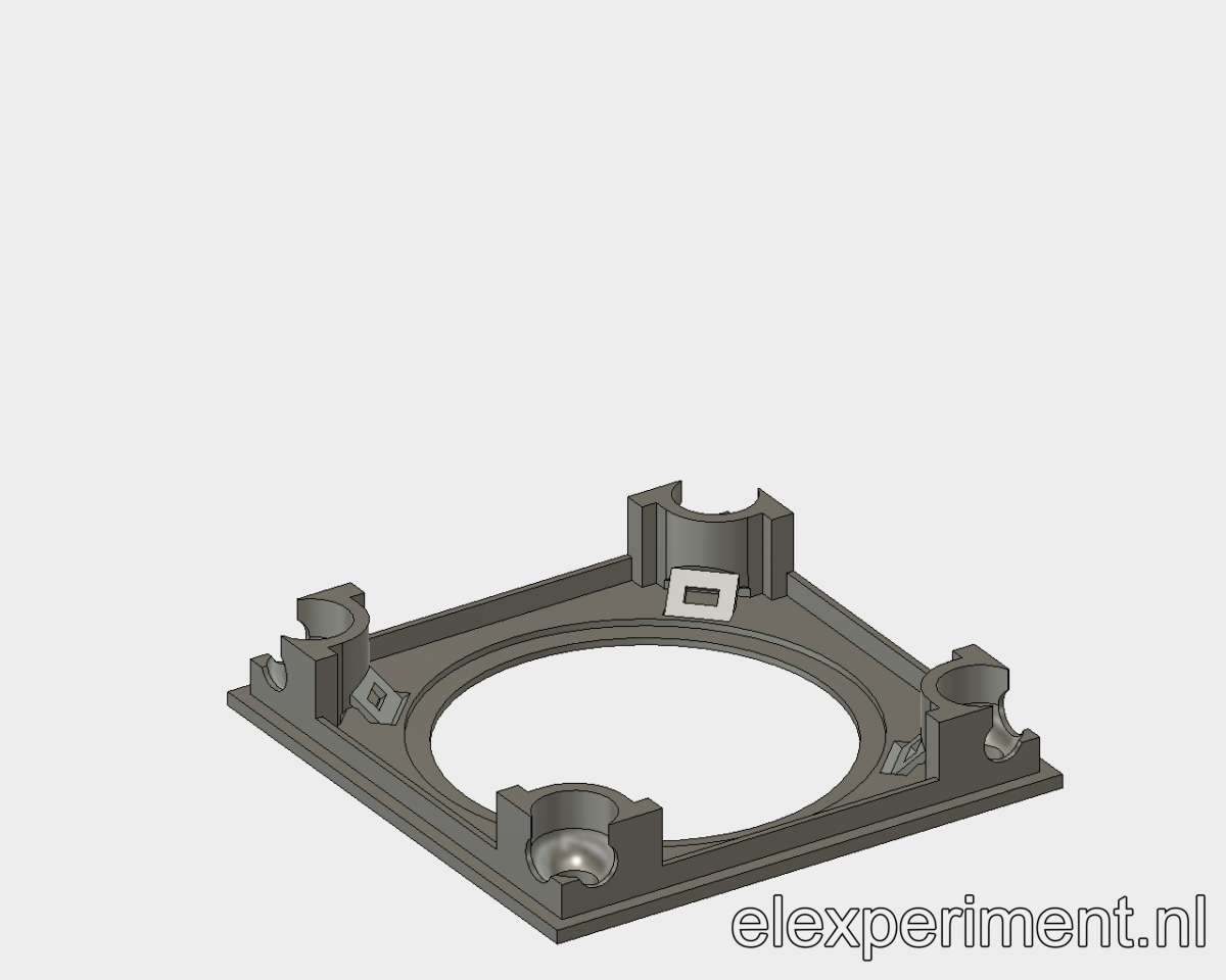
With this hurdle taken, on to the next step: designing the cubes themselves! For this purpose, Fusion 360 was used. Design files, and STL files for 3D printing, can be found at the end of this page. The design has had a lot of iterations and revisions, to optimise for printability, looks, etcetera. This results in a two-part design: a frame, and a lid. They are quite similar, except that the lid has fewer sides. The idea is to mount (neutral white) LEDs in the four corners of both the frame and the lid. That is where the small “rectangles with holes” are for.
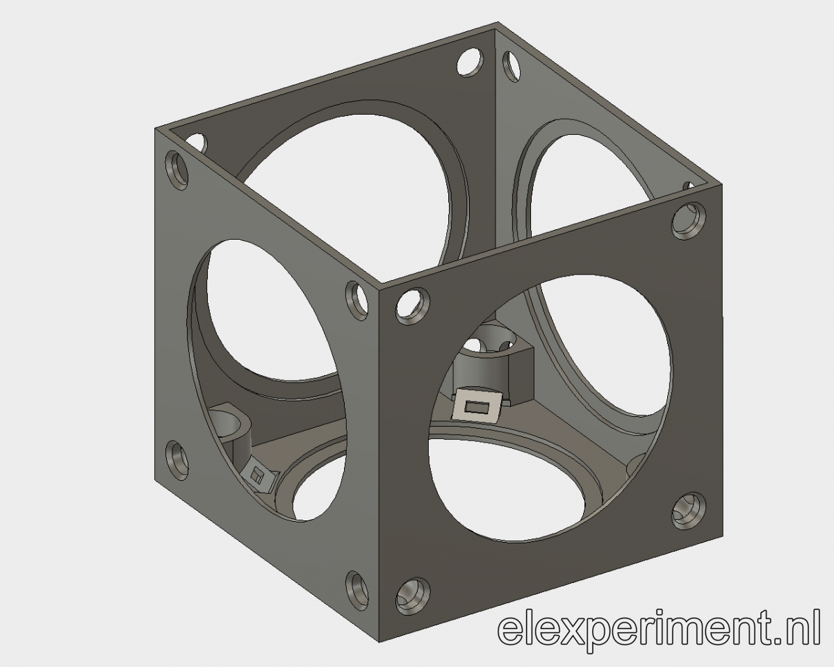
The LEDs are pre-bent, such that they can be pushed in the holes, after which the leads are used to pull them flush.

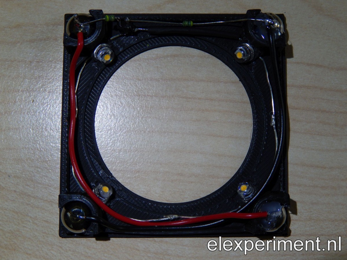
As can be seen above, four LEDs are connected in series. The remainder of the (quite simple) electrical circuit consists of a full bridge rectifier and two resistors. The rectifier has the purpose of reverse polarity protection: in every possible way of connecting, the LEDs get a positive voltage. Two 50 Ohm resistors are used to connect the steel balls to the full bridge rectifier. In this way, no additional wires are required for connecting the LED circuit. Finally, steel balls are connected diagonally (which also holds for the frame and lid), such that current can be conducted from one side to the other side of the cube.
Before mounting the electronics, one step has already taken place: painting the insides of the cube with white spray paint, for increasing optical efficiency.
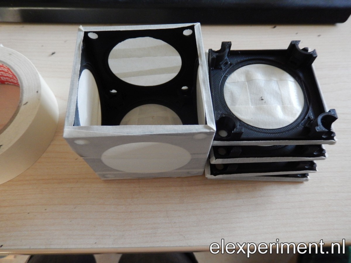
Now it is time to mount some material that diffuses the light. Ideally, some acryllic diffuser, laser cut to shape, would be used for this. However, this wasn’t possible in the available time, which is why I opted for tracing paper. This paper, which I previously used for PCB production, is quite translucent, yet diffuses the light quite well. The paper circles are then glued to the frame, for which a (3D printed) disc is used to nicely fix the paper.


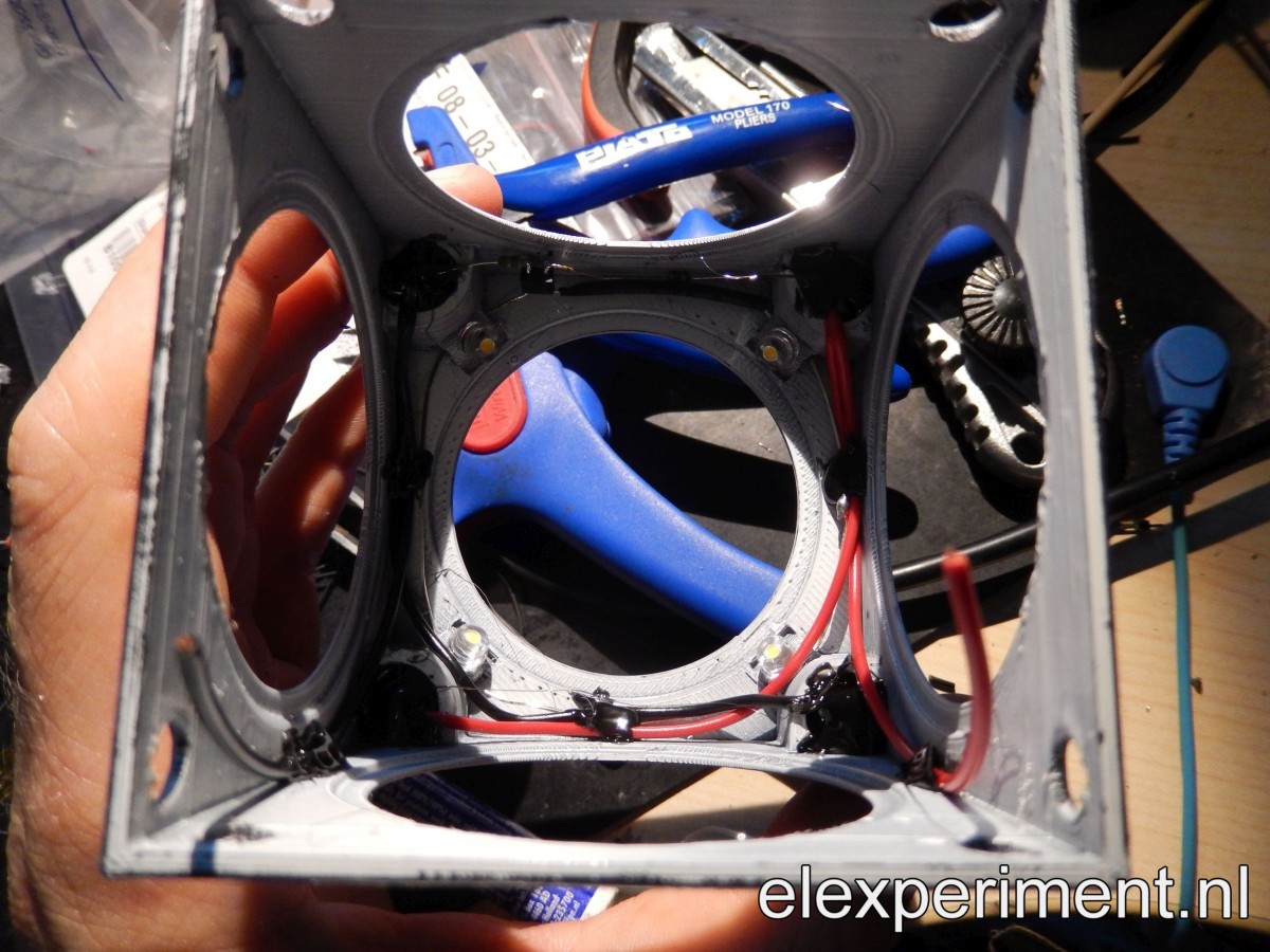
The final step in producing the cubes is then to connect the frame and lid (by soldering some wires), and closing and gluing afterwards.
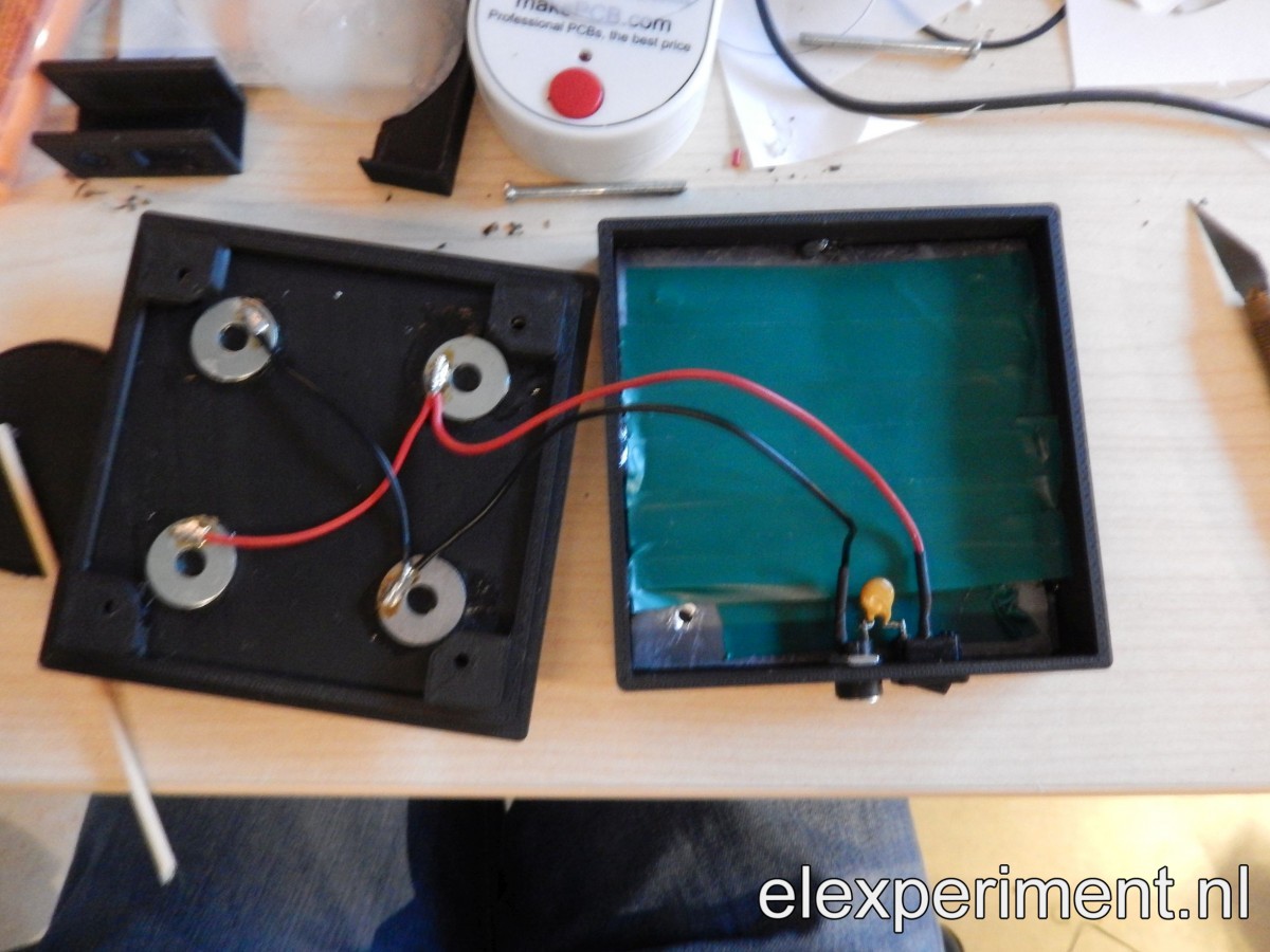
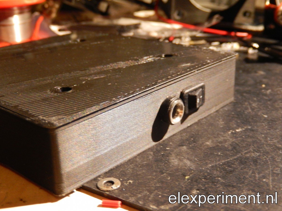
Besides the cubes themselves, something to mount them (and supplying power to them) on is also required. The base is also 3D printed, after which some weight is added (by means of lead) to stabilise the construction. Furthermore, a power socket, switch and polyfuse are added. Four washers, that are glued with the base lid, provide electrical connection (via magnets) to the first cube. The cubes are powered via a 15V, 1.2A power supply. In hindsight, this adapter appeared to be a bit overkill: the cubes consume only about 50 mA each. On the other hand, this allows to use more than 20 cubes :).
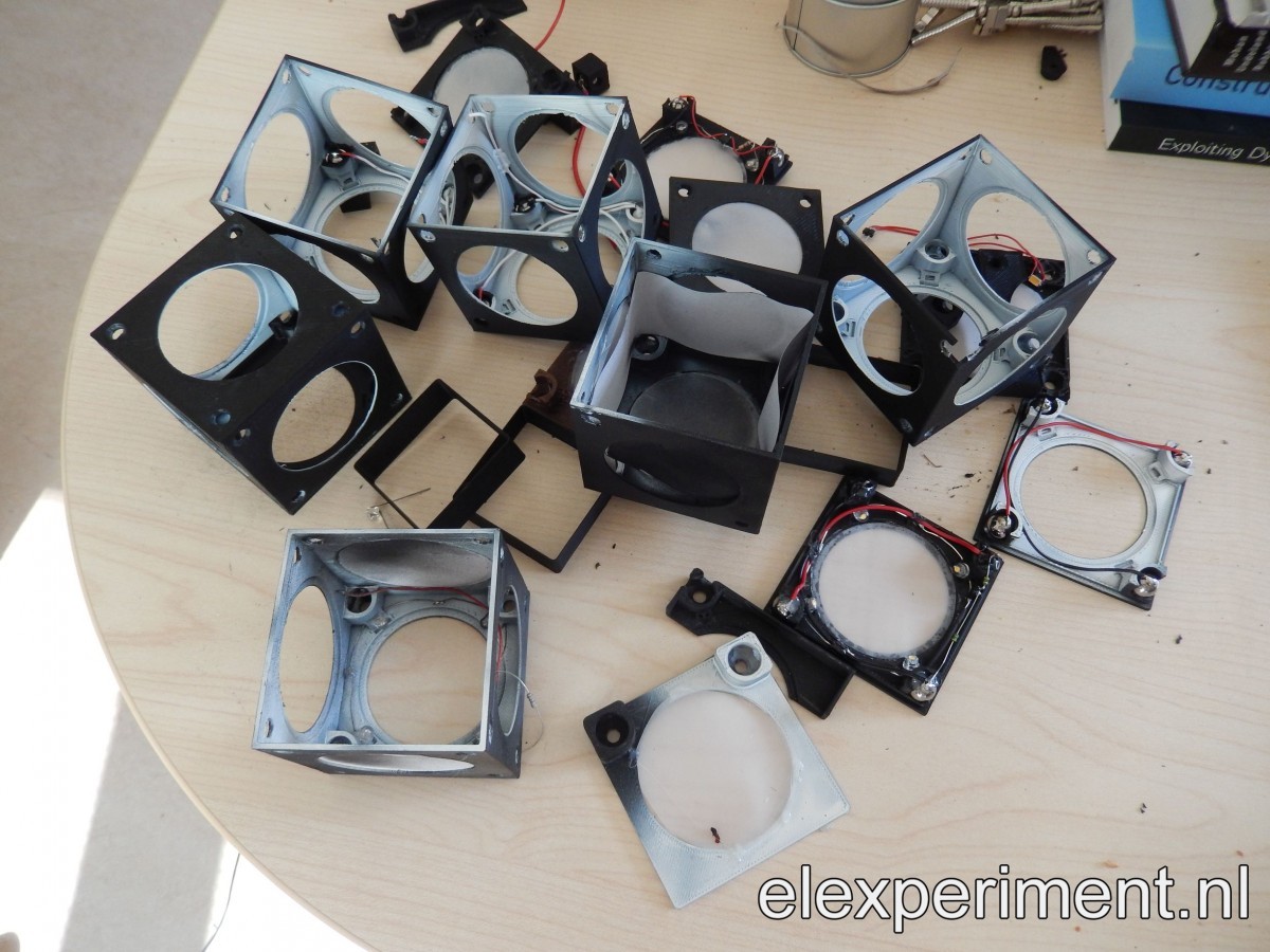
All in all, the project was quite a success, which did also take quite some time. To illustrate the amount of iterations (and the advantage of 3D printing) a bit:
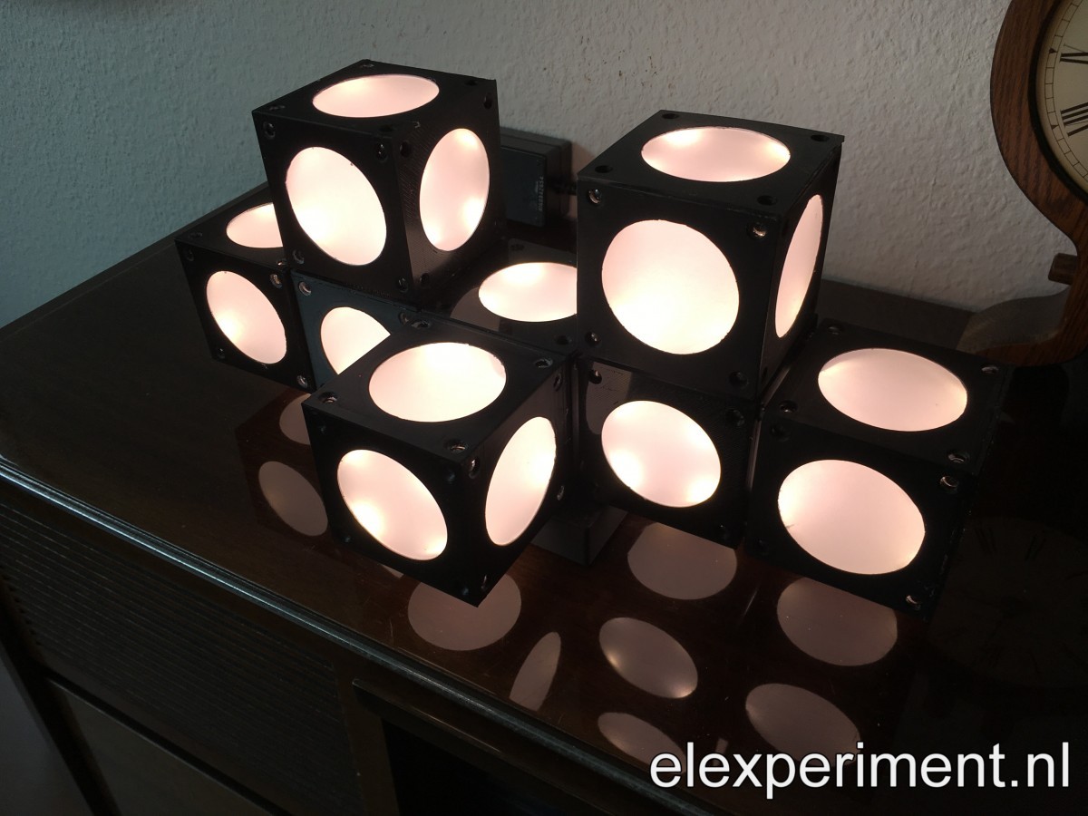
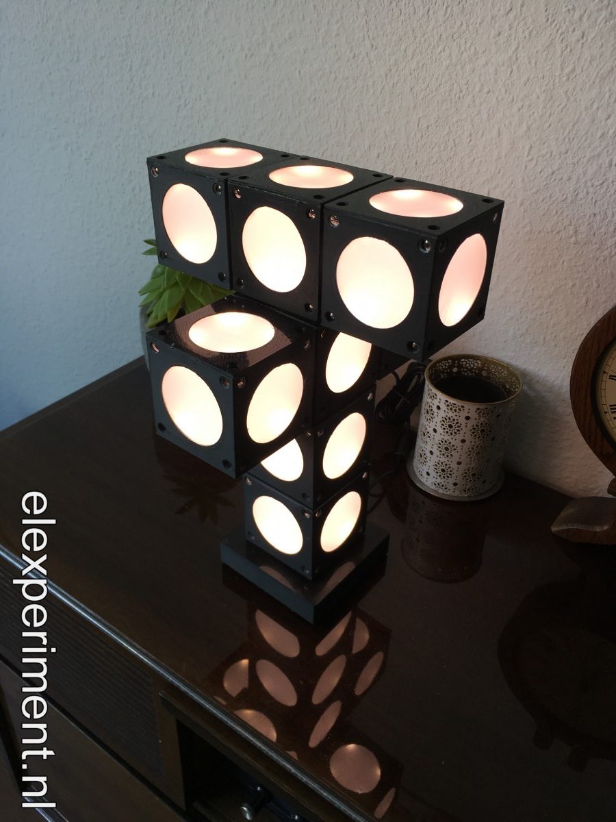
And finally, the end product, which is now shining somewhere else.
Source files (Fusion 360) and STL files for 3D printing can be downloaded here: CubeLamp
Pingback: CubeLamp: introduction - Elexperiment.nl
Dit kwam me al zo bekend voor… Inderdaad, eerder gezien in het show-your-projects topic. Mooi!