For quite some time, I’ve been developing a two wheeled balancing robot. You know, like a Segway. But in this case it is somewhat smaller, as to minimise damage when hitting something at high speed. That happens rather often, due to the very high maximum speed of this robot.
This post will cover the architecture of the robot, explaining all ins and outs. Many balancing robots have been made before, but this one has some nice features that make it very well behaved. Also, everything has been designed to make the robot easy to replicate. As one of the goals of this project is to get other people to work on the robot, all source files will be made open source. Also, in a future post I hope to document how to build one.
Just to be clear: the purpose of me making this project open source, is not for people to get such a cute, fun robot, that they’ll play with and then never use anymore. The purpose is to educate other people, to share knowledge, and to create and extremely good performing robot together. Just because. Because developing technological things without purpose is fun.
Basics
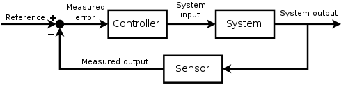
In order to balance an unstable system, negative feedback is required. The diagram below illustrates the approach. Besides a feedback loop, a sensor to measure an error (or rather the sytem response), and an actuator to minimise the error, are required.
Sensing and actuation
Getting a sensor with sufficient accuracy and bandwidth is relatively easy; in this case the well-known (and mostly cheap) MPU6050 IMU is used. The accelerometer provides a long term stable, but noisy signal, especially if you accelerate fast. The gyroscope on the other hand gives an accurate, high speed signal, with drift however. Combining the two using a simple complementary filter gives a stable signal, representing the angle of the robot.
Next, an actuator needs to be selected. A common choise is a DC motor, for example for its low cost or simple control. However, a DC motor has in general a too low torque to directly drive the wheels of the robot. A gearbox is used to increase torque, but several disadvantages are introduced as well. Cheap gearboxes have severe backlash and friction, which make the control loop non-linear, and therebey making everything a lot more complicated.
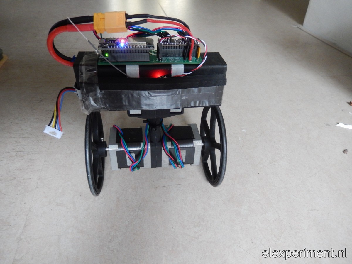
This is where the stepper motor comes in. This idea isn’t new, serveral other examples of balancing robots with stepper motors are available. For some examples, see here, here or here. Steppers are quite suitable for the job: direct drive, relatively high torque, low inertia (which isn’t true for a DC motor with high gear ratio), and no backlash. Stepper motors are commonly used in for example 3D printers, and can hence be found for a low price (about €10 each). Driving the steppers is also done with 3D printer related parts. A so called step stick, containing a DRV8825 IC, arranges all the power electronics, accepting a logic step and direction input.
Software
Then comes the software. In my opinion, this is the part where the most difference can be made. The above description holds for a lot of balancing robots. With suitable software / control implementation, a lot of differentation can be made. The software of this robot runs on an ESP32, a dual core microcontroller with integrated WiFi and Bluetooth. Using an ESP32 allows for several nice tricks, such as control with a smartphone via WiFi / Bluetooh (not implemented yet), OTA, wireless data logging, etc.
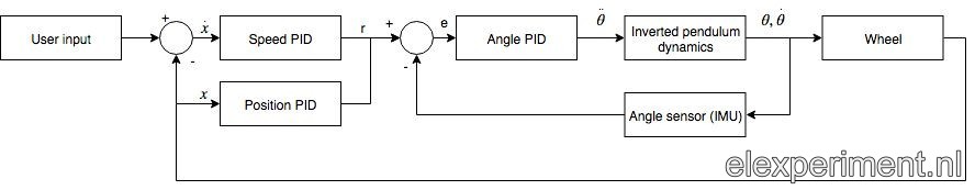
Currently, the software runs two control loops at 200 Hz. See below for a schematic view of the two (cascased) controllers. The first control loop tries to minimise angle error, i.e. keeping the robot upright (in case of a zero reference). The second control loop either controls position or speed, depending on user input. If no input is present, position is regulated to be zero. Otherwise, the outer controller manipulates robot angle to obtain a speed equal to the speed setpoint. To give an example: if the robot is standing still, and a positive (forward) speed setpoint is given, the robot tilts forward until it reaches the desired velocity. When standing upright, the inner control loop moves the wheels backwards, such that the robot will tilt forward.
Electronics
For powering the robot, I currently use a 6S1P (24 V) 2650 mAh LiPo battery. That’s quite a big one: it allows for up to 5 hours of driving time. So, such a big battery is not strictly required. Besides this battery being relatively cheap (in Wh/€), a big mass on top of the robot makes the robot fall “slower”. This makes stabilising the control loop easier, and, it also looks more natural in my opinion. A sturdy case has been 3D printed to fit tightly around the battery, to allow for protection. The high voltage of the battery allows the steppers to be run at extremely high speeds. Note that 6S is over the top, and 3S will give sufficiently high speeds.
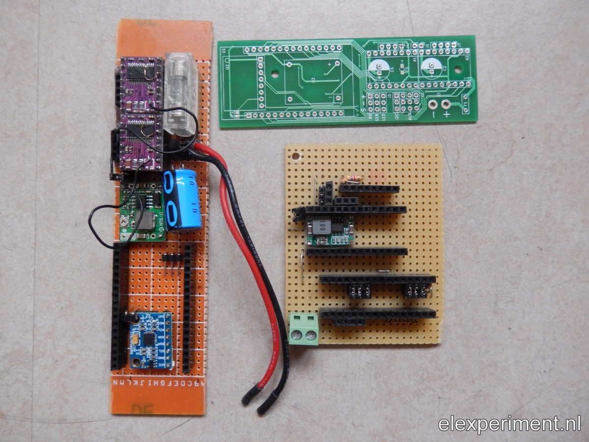
The last part to add is a PCB. For the first robot versions, I developed some experimental PCBs. For the current version, I’ve drawn a simple PCB, based on commonly available modules (IMU / step-stick / ESP32 dev board), which allows for easy assembly. The PCB is drawn in KiCad, which is open source software. In case you want to make something yourself (on an experimental PCB), see the PDF of the schematic in the Git repo.
Some PCB history
The total cost of the robot is quite limited due to use of standard components. Electronics are about €10, steppers €10 a piece, battery between €5 and €30. The frame can be printed cheaply (see Git repo for source files), or simply zip tie everything to a piece of wood. Currently I use an RC transmitter / receiver, which drives the cost up, but as soon as WiFi/Bluetooth control is implemented, it isn’t required anymore.
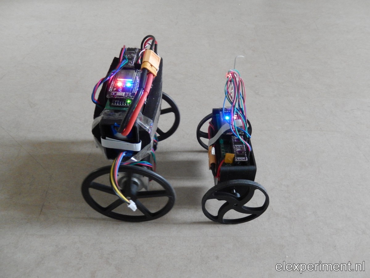
To end this post, some more pictures of the complete robot(s). Yes, it has a small brother :).
More info
Source files can be found in the Git repo. It is highly appreciated if you contribute to the project!
The subolders in the repo also contain readme files, explaining how to assemble the electronics, and how to setup the software environment.
Hello.
I saw your high speed balancing robot in youtube.
it is interesting for me and I want to do this project if you let me. ^^
Could you send me a PCB ( current version )?
Now i am buying resource motor and etc.
Thanks for your video.
Friend I am having trouble setting PID can pass your default settings?
Hi ! Congratulations!!!!
I really like your project! And I want to do the same.
What is the model of the motor stepper that you’re using ?
Thank you.
Thanks for your reponse! I use Nema17 stepper motors (the ones typically found in a 3D printer). I’ve used motors with a length of 34, 40 and 48mm, all work ok. I think 40mm length is a nice balance between weight and torque required for this application.
Thank you.
Friend excellent project. I’m mont one together for my son. I installed Atom but in the compilation it presents errors. Did you need to install any external libraries?
Hi Leonardo, thanks for your response! I think your error is caused by me not having included the Streaming library; I installed this library globally (which is bad practice). See the latest commit in the dev branch: https://gitlab.com/kloppertje/balancingrobot/tree/devel
If it still doesn’t work, please post (or better, mail) the specific errors you get. Also, I can recommend VSCode, it works a bit better compared to Atom with PlatformIO, in my opinion.
lib\AsyncTCP\src\AsyncTCP.cpp:259:27: error: field ‘call’ has incomplete type ‘tcpip_api_call’
I solved the error above. I upgraded the AsyncTCP library to 1.0.3 now I’m having this error. lib\I2Cdev\I2Cdev.cpp:276:75: error: no matching function for call to ‘min(uint8_t&, int)’
no matching function for call to ‘fastStepper::fastStepper(int, int, int, bool, void (&)())’
Friend excellent project. I’m mont one together for my son. I installed Atom but in the compilation it presents errors. Did you need to install any external libraries?
Hi, exccellent Job!, i try build it, but when build the project on platformIO show this error in I2Cdev.cpp:
“no matching function for call to ‘min(uint8_t&, int)’
In Line 276:
for (uint8_t k = 0; k < length; k += min(length, BUFFER_LENGTH)) {
Any Idea?
Thanks!!!
Hello,
congrats to your cool project and thanks for sharing it! I have onestion: which polyfuse (how many amps) did you use?
Do you have a pcb left for sale?`
regards
Robert from Austria
Hello Wouter,
thanks for the PCB. Now i am fighting a bit with the Stepper Code in the Loop i found this lines.
motLeft.update();
motRight.update();
// updateStepper(&motLeft);
// updateStepper(&motRight);
In my case it seems that ust the motLeft produces an appropriate stepper clock on the gpio pin the motRight gpio is quiet. However the direction pin of the motRight is working. If i flip the update-Statements (motRight first), in all cases the first is working. It seems to me that something with the timer/ISR is not working. Do you have any hints regarding that problem?
BR Robert
Hi Robert,
I haven’t experienced these issues before. Are you using the devel branch (which I recommend)? And, have you changed any of the pins used for step generation? Maybe something goes wrong in this function (lib/fastStepper.cpp):
void IRAM_ATTR fastStepper::timerFunction() {
// portENTER_CRITICAL_ISR(&timerMux);
if (!pinState) {
_step += dir; // Step is made on rising edge
GPIO.out_w1ts = 1<<_stepPin; pinState = 1; } else { GPIO.out_w1tc = 1<<_stepPin; pinState = 0; } // portEXIT_CRITICAL_ISR(&timerMux); } You could for example try using digitalWrite (which is probably a bit slower). KR Wouter
What type fuse should i use instead of F1 polyswitch? i can’t find it in my country. Ampere or volt?
Depends on the supply voltage. Typically, two stepper motors consume 10-15W. So, at 12V that’s roughly 1A. So, a polyfuse with a rated current a bit above that, say 2A, should suffice. And the rated voltage should then be higher than 12V. But again, it all depends on the choice of input voltage.
I am trying to do the same as yours. Will work with 6s lipo. How many volts and amps do you recommend? There are thermal and glass fuses with legs but I don’t know how many degrees Celsius or amperes (volts) i will use.
https://www.robotistan.com/5a-amper-1?OM.zn=CategoryPage%20-%20CatTopSeller-w21&OM.zpc=14451
this one has 2, 3, 4, 5 A.
5A enough for 24V?
Finally, I am confused about two points.
First, in the pcb readme file, you said “You can de-solder the current adjustment potentiometer on the stepper driver breakout boards. Add a wire to the wiper terminal, and connect the (two) wires to J4”. As far as I understand, J4 and J7 for the stepper motors output connections. Will the cables from the stepper driver breakout boards be connected to J4 or J1?
The second is JP1. I tied the decay mode pin of the DRV8825 to VCC. Will JP1 tips be soldered?
Thank you for your support.
Hello Wouter,
yes i am on the devel branch. I have written an alternative loop-function with just a simple test code in it. And i am counting how often the IRAM_ATTR motXXXTimerFunction() are called.
https://github.com/SrR0/BalancingRobotESP32/blob/master/src/main.cpp
The counter of the left motor interrupt is counting up the other stays 0. If i flip the first
motLeft.update();
motRight.update();
to
motRight.update();
motLeft.update();
the right motor output is working. The Timer and portMUX stuff is a bit suspect to me. It seems the first timer functioncall is locking something with the timer of the other motor
BR Robert
Hi!
in the meantime i found out that if I disable the timer before enable it, it seems to work. So the second timerAlarmEnable without timerAlarmDisable before does not work. I have no idea why.
fastStepper::update(){
…
timerAlarmDisable(_timer); //just for testing todo: cleanup
timerEnable = 0;
if (!timerEnable) {
timerAlarmEnable(_timer); // Re-enable timer
timerEnable = 1;
}
} else {
timerAlarmWrite(_timer, 100000, true);
timerAlarmDisable(_timer);
timerEnable = 0;
}
BR Robert
Hello,
I used the PID controller class in a different projekt and I noticed that the behaviour when using the integral term of the PID controller was a bit weired. The lower I set it, the more powerful was the effect. I didnt understand the calculation oft the integral term:
void PID::updateParameters()
{
_if = _dT/Ti;
_df1 = Td/(Td+N*_dT);
_df2 = Td*N/(Td+N*_dT);
}
the higher the Ti ist the lower is the effect when being multiplied with the error of the comparation between setpoint and feedback-input.
I changed it into
void PID::updateParameters()
{
_if = _dT*Ti; //higher value of the Ti and longer sampleperiode should increase the effect of an error
_df1 = Td/(Td+N*_dT);
_df2 = Td*N/(Td+N*_dT);
}
Seems to work for me. Maybe I did not understand the whole therory 🙂
BR Robert
Hi Robert,
This is just a matter of definition. Sometimes people use “gains”. I like to look at the PID controller in the frequency domain, and in that case using time constants (Ti and Td) makes more sense. A lower Ti means it will work up to a higher frequency, i.e. it will be more aggressive. The same goes for Td, a lower time constant means a higher frequency at which the damping action is active. So, in this case, a higher Td gives the feeling of “more damping”, which probably is a bit more intuitive than the behaviour of Ti.
KR,
Wouter
Hi,
I am tryng to open pendulumRobotModule.sch on Eagle. But it gives me this error and not opening.
Loading C:/Users/ati/Desktop/Hızlı robot/balancingrobot-master/PCB/pendulumRobotModule.sch …
Error:
line 1, column 1: Start tag expected.
hello, i want to make one. do you please send me the board if it possible?
Hi Wouter
First of all a big thank you for sharing this project! I’m building one. So far everything is OK. But I have two places in “main.cpp” which I do not understand and which platformIO shows as faulty.
Source: https://gitlab.com/kloppertje/balancingrobot/-/blob/devel/Software/src/main.cpp
1. In line 524: plotData; -> “The default constructor of” “union ” “cannot be referenced”
2. in line 718: accAngle = atan2f ((float) ay, (float) az) * 180.0 / M_PI – angleOffset;
-> “M_PI” is not declared or otherwise referenced. What is that value?
Best regards
Dave
Hi Wouter,
I have built one working with 24v and its working excellent. But i can not activate the servo. Could you help me?
Hi Wouter,
Great build. I love the speed & stability.
Do you still have PCB’s available? I’m in the US. Is there a way I can pay you for the PCB & postage?
Also, I have 38mm NEMA17s. You had mentioned a 42mm being good for torque. I take it the lower torque would affect higher speed operation but would be OK at lower speeds?
Dankjewel!
Hello! Your robot does not lose balance if it is tilted left or right?
Depends on the orientation you’d be pushing in. And if you push hard enough, it’ll fall. It can handle some slight pushes though.
Thankyou for your excellent design. It works really well. I’ve been looking at your code and have learnt a ton of neat tricks e.g ota flashing, ibus, mulicore coding, and was shocked that you even have a html editor tucked on board!
Not sure whether this comment system will allow me to put a link to a YouTube video, here goes:
https://youtu.be/_oza35BNgYA
I do love the esp32. Where did you learn about spiffs and mdns. Totally new to me!
Thanks for the nice feedback! It’s really nice to see a video of a well operating robot :). I think, besides the usual searching on the interwebs, a lot of things are to be learned from Andreas Spiess’ Youtube channel: https://www.youtube.com/channel/UCu7_D0o48KbfhpEohoP7YSQ
Hi Wouter, i have error 404 when i try to connect ip adress 192.168.4.1.
on the terminal from platformio the message: Loading index.htm.
What could be the reason? the build is without errors.
greetings, Henk
Hi Henk, did you upload the file system?
Hi, i built this project and it was awesome. Thank you!!
It felt nice seeing the robot balance for the first time.
I did some modifications though due to different hardware available to me-> stepper driver changed to tmc2208 witj UART control and currently im working on a bluetooth joystick control from an android app. encountered a problem on program size due to addition of serialbluetooth library but i think i can make it work after modifying the esp32 partitions.
I got some questions on the Ibus input range. Is it from -1500 to 1500 for the speed and steer?
Nice to hear that you can make use of the hardware/software! How do the TMC drivers work? Does it give a smooth/silent response?
IIRC IBus variables are in the range of 1000 to 2000 (so similar to PPM, which goes from 1000 to 2000 us, I think).
Is the pcb ready for sale?
Nope, out of stock.
Awesome model! There’s a few self balancing robots to watch on YouTube. Yours is clearly much quicker that the rest and is super smooth and responsive, so what makes the difference? Those thin wheels on a hard surface? Using an ESP32 as opposed to an Arduino which is what most people use? I wondered about using the 6S battery but the NEMA 17s only run 2.8V so I’m assuming it’s not that. Or is it the pure weight of the 6S cell that helps? A combination of these things? What’s the secret?
Thank you! Difference: a lot of time invested in the project, I guess :). And some thought put in the control process. I think the main influence is the actuator: the steppers have almost no backlash, low friction, and respond (up to a certain frequency) well to the command given. Also, the robot only works well on flat surfaces. Due to the limited torque of the steppers, not much disturbances can be handled. And btw, “performance” could be way better, e.g. by tuning in the frequency domain, or by using a better actuator (brushless / PMSM motor). But that would require encoders and FOC, which would make the project much more complicated (and expensive).
About the battery: the steppers have a rated voltage of say 2.8V, but this is purely the I*R component (i.e. resistive). The stepper driver works as a buck converter, so it just converts the high voltage to a lower one. Also, at higher speeds, you’ll get (lots of) back-EMF, hence the battery with the high voltage. Although, in general, 3S would be sufficient I think.
Hi Wouter!
I used the PID controller class in another project. And I had problems using the integral term of the PID controller, and even used the advice written above, but nothing helps. I also did not understand what the parameters N, R and MAX MIN. Can you recommend any manual? Sorry for my English)
Here is my project: https://www.youtube.com/watch?v=j_3n7zj0gfw
More photos and videos: https://t.me/bauritotvchat
Great stuff man.
Have most the parts already. Missing parts on order, ✓
I sent your PCB design to get made. 3 on the way, ✓
Had a couple issues with dependancies in the code but tracked down issues and it’s all uploaded to the ESP32. ✓
I had to grab a modified i2cdevlib for anyone running into compiler errors with main branch, take a look at: https://github.com/jrowberg/i2cdevlib/pull/530/commits. It worked for me. ✓
I can’t wait to get into this!, I have ideas…. I will report back ( ͡° ͜ʖ ͡°)
Thanks for all the great info
Cheers.
Getting there. No driving around yet, still trying to tune it. I can’t get the 1000 to 2000 speeds from controller to cooperate but that’s for another day.
Thanks again.
https://youtu.be/efaiDyZZ9QM
Had to get the control working. So fun!!!
https://youtu.be/blcau55bhf8
Nice to see your progress 🙂
Hello !
I’m just a beginner in electronics and I’m looking for a two wheels robot as a first project to learn.
Yours looks really nice ! Responsive ! Fun ! 🙂 congrats ! I love it 😻
I’d like to do the same if you allow me 🙂
Sorry in advance for my newbies’ questions …
Have a 3D printer for body, wheels, … and an Amazon account ^^ for electronics but I don’t know anything about PCB :/ you created your own one !? I can’t do that 🙁 can I use something else ?
Very thanks for your sharing.
Cheers
Hi! For the PCB, you could make something yourself with some proto PCB (“soldering breadboard” / don’t know exactly what it’s called). One of the pictures in the article shows this approach. The components and connections are relatively straightforward; for a list of all components see https://gitlab.com/kloppertje/balancingrobot/-/tree/devel/PCB
Hi Wouter,
I built “mine” from recycled parts (CNC shield, NEMA 17 steppers from a dead 3d printer) and the chassis from “Fischer Technik”, a kids building blocks toy system.
After taking much too much time before finding out that the “enable” pin needes to be pulled up, it now works like a charm. Also, I didn’t manage to set the PID right for the Fischer Technik wheels, so I printed yours and it works even better.
Thank you SO MUCH for publishing your awesome code and sharing the CAD files! It seems the steering via websocket is deactivated and I received only errors when trying to “revive” it by uncommenting the relevant sections.
So, I implemented my own steering code; it looks so crude next to yours.
However, it works and my kids love to play with the bot.
Again, a big thank you and all the best-
Sebastian
Hi Sebastian, nice to hear that you are tinkering around. Have fun!
Hi Woulter,
thanks for the excellent code!
I am currently working on changing the suspension axis so that it can easily overcome small steps and thresholds. Like in this video:
https://www.youtube.com/watch?v=gs_H3TOrLxw&feature=youtu.be&ab_channel=RobotEnthusiast
I already tuned it and it can drive and it also manages small thresholds. I would just like to make it so that he does not lean forward when he drives forward. Is this possible and if so where do I have to start?
Thank you very much! Tobi
Hi Woulter,
thanks for the excellent code!
I am currently working on changing the suspension axis so that it can easily overcome small steps and thresholds. Like in this video:
https://www.youtube.com/watch?v=gs_H3TOrLxw&feature=youtu.be&ab_channel=RobotEnthusiast
I already tuned it and it can drive and it also manages small thresholds. I would just like to make it so that he does not lean forward when he drives forward. Is this possible and if so where do I have to start?
Thank you very much
Hi Tobi, I’ve seen the video before and it’s quite an intriguing approach. “Basically” it’s just a double pendulum, of which many examples can be found on youtube; a double pendulum can be made stable by means of feedback control. The new thing with this robot is that there is a belt drive between two axes of the double pendulum.
Where you start depends on what you want to achieve. If you want to fully grasp the system, develop system dynamics and simulate the system etc. I think it’d be wise to make some sketches first, to get a feeling of what’s happening. At the moment I don’t have intuition for this robot and I don’t want to get involved in it. But you could for example sketch torques/forces on the wheels/link/main frame in various positions: when the robot is standing upright with the link vertical, or when the robot is upright with the link horizontal. Just fiddle around and get a feeling for the system. Or, look up the paper :). I believe there’s a paper on the web somewhere. Ah found it: https://ieeexplore.ieee.org/abstract/document/6631384
Hi Walter, thanks for your answer. I think I did not express myself clearly. I have already rebuilt the axis and experimented with several gears and belts and I have the robot so far that it stands straight and can climb small steps. https://vimeo.com/515034525
The only problem is that it tilts over at higher steps. I think it is possible to compensate the tilt via software. I will do more research on the double pendulum and look deeper into it.
Thanks for the hint! If I have a useful result I will write it here.
Thanks a lot!
Very cool! Design looks also nice and clean. I shared your video with some people as I’m quite fond of the concept and your execution :).
Hmm let me think. Should indeed be possible to correct for tilt, but the control parameters will be very different as the wheels are blocked. Basically you’ll be moving the lower link to keep the upper body upright. My intuition says you can only keep the robot stable if the lower link is mostly vertical. If it were horizontal, you could change the angle of the lower link but the upper body will not move horizontally i.e. the system is not controllable.
If controller parameter switching would indeed work, the trick is how to detect (quickly) if the wheels are blocked. Maybe it would help if you add another IMU in the lower link? If you’re good with controller design you could also use this to prevent the high frequency oscillation you sometimes see in your video.
Also, if you want to play around maybe it would help to simulate. Last week I was playing around a bit with Matlab / equations of motion and animating the result. Let me know if you speak Matlab 😉
Also, maybe it’s better to continue (if you like) via e-mail? wouter@elexperiment.nl
In 2003, I saw a video of nBot. It was a two wheel self-balancing bot. I wanted to make one so bad. Never got around to it. A few months ago I saw your video and said to myself, “DO IT!”.
I had a spare ESP32-DEVKITC-32D so I went with that. Modified your schematic for the different pin outs and made a board. Today, I soldered the ESP32, MPU-6050 and the DRV8825. After calibrating the Gyro and Accels ( making sure the motors rotated in the right direction) it balances! I am so very pleased! I need to add the RC control, battery monitor and maybe distance sensor.
Thanks
Hello Wouter!
I have been researching many different two wheeled balancing bot designs and yours is by far my favorite! I have a number of parts on order and am starting to print the files you have shared. I am curious, what did you use for the tread on your wheels? It looks like you may be using a large rubber o-ring. Is that correct? Can you provide dimensions? Did you try printing a tread with flexible filament?
Cheers,
Robert
Hi Robert,
Sorry for the late reply, apparently I missed something. Indeed, I use O-rings, diameter is 80mm (for the smaller wheels) and 110mm for the larger ones. I haven’t tried flexible filament, as the O-ring solution works quite well (if I vacuum clean so now and then, otherwise the robots start drifting :)).
Hello, how are you? I congratulate you, excellent project. I’ll tell you, I did it and it works very well, it keeps the balance, I push it and it stands up, but I have a problem. I bought a 6-channel RC FS-i6X and when the robot is connected it loses its balance and falls and I’m sorry I’m not an understanding in the art of programming I just really like electronics as a hobby if someone could help me solve this problem I will be very grateful
Thanks for the appreciation, and good that you could make use of the code! Did you try setting the robot upright manually after connecting the receiver? Also, have you tried the latest devel branch (instead of master)? If these two things don’t help, you can “debug” by placing serial print commands at tactical places in the code, so that you can learn why the robot doesn’t work as you want it.
Hi Wouter, you project is really fantastic, I have tried to set up a selfbalance car for long time, but it is very difficult to reach the speed like your case, when the car speed up, it tends to fall up shortly. Thanks for your opensource code, I get chance to learn how is your’s work, one thing I don’t understand is line 683 pidSpeed.input = -avgMotSpeedSum / 35.0;
and line 703 avgMotSpeedSum += pidAngleOutput / 2
why you would like to devide the avgMotSpeedSum by 35 and divide pidAngleOutput by 2, if you get time to have a look my question and reply to me, it will solve my confusion much quick, thanks!
Stephen
Hi Wouter, you project is so amazing.I have some problems.What is the straight line speed of the car and what is the turning speed? If you get time to have a look my question and reply to me, it will solve my confusion much quickly, thanks!
Cherry
Hi Cherry, can you elaborate on your question / what is the problem? Straight line and steering speeds are not very exactly defined. There are some scaling factors applied here and there. User input is from -100 to 100, and to what speed that corresponds in SI units I cannot exactly tell you 🙂
Hi Wouter,
congratulations to this excellent balancing robot! I like very much the realization with the ESP32 and the robot’s webpage. And I learnt how to use Visual Studio and platformio, which I’d like to thank you for as well.
I have built a prototype on a breadboard and have calibrated the gyro and acc, but the robot shows strange behavior. The motors start and immediately stop right after, and only give a beep sound. I have uploaded what it does here: https://youtu.be/JTLJ2uNZDOM
Do you please have me a hint, what might be wrong?
Thanks a lot!
Dirk, from Munich
I have just built my robot using your design and source code. It runs great on smooth surfaces like linoleum flooring, hardwood flooring and carpet. When I try to run it on asphalt or concrete it make one attempt at correcting its balance and then forcibly crashed to the ground. I first thought that maybe the steel reinforcement in the concrete was causing the problem. But when I place a flat piece of wood on the concrete the robot behaves well. Now I am thinking that it is the texture of the surface; (rough vs. smooth) that is confusing the IMU. I’m going to take a look at the IMU and see if there is some kind of filtering that can be turned on/set/added. Do you have any ideas?
Hi Charles. I don’t have experience with this issue, but I do have some ideas on how to potentially tackle it. A rough surface will probably give a lot of noise on the accelerometer/gyroscope. There is an option to adjust how much the IMU relies on the accelerometer vs. gyroscope. Additionally, you could implement some simple filters (e.g. low pass filter) to filter out potential noise. However, I’d like to suggest to use the “wireless plotting” functionality, see “plotting signals” on https://gitlab.com/kloppertje/balancingrobot/-/tree/devel/Software
KR,
Wouter
Thanks for the info. I’ll let you know how it does.
Thanks, Charles
Hi Wouter,
Hope you’re still around! Thanks for getting this all put together, I’ve cloned your repo basically completely the hardware build you’ve created but am stuck your explanations in a couple of places:
Where exactly in J4 should I connect the wires coming from the DRV8825 wiper terminals (there is a wire soldered to each terminal, independent of each other). I’m confused here as J4 connects directly to the stepper motors based on the schematics.
When uploading the project, you state that we need to uncomment the lines with the host name and IP, but this throws an error saying that port is already occupied by COMXX, can you please provide some clarity on this?
I’m really looking forward to getting this completed (Orings for the wheels arrive today I hope) and I hope to hear back soon. I know these are really simple questions but I am having trouble understanding the instruction in those parts. Lookikg forward to contributing soon, I appreciate and look forward to your response!
Short reply (typing from smartphone): j4 should be j1, good catch! In one of the pictures this is visible.
For uploading, maybe it’s a matter of commenting the line which specifies a com port? It’s been a while since I’ve used OTA. Also, with the latest ps3control branch I think OTA doesn’t work anymore, I’d recommend using the com port. It seems I need to update the instructions a bit 😉
Awesome thanks for the quick reply! And yes, I was going back and forth between the picture, schematics and the instructions while scratching my head on the J4 thing. Should be up and running in no time now! Haven’t used OTA before but once I get to it I’ll try to figure how to use it correctly, shouldn’t be too tough. Though I’m referring to the Serial/USB upload for the first time, should I uncomment the hostmame/ip info for that first upload? If so it doesn’t seem to like that.
Thanks a lot for the awesome project
I just didn’t understand a few things i have Nodemcu32s mpu5060
but imu.initialize(); no working Why
please explained
Hello,
Your balancing robot is really impressive ! (Best DIY I saw)
3 months ago I started a similar project (balancing robot) with ESP32-S3 + esp-idf + freeRTOS + bno085 (IMU) + nema motor.
And a week ago I discovered your project which inspired.
In view of your graphical interface (plot.html), I decided to integrate a web server to have a real-time visualization like you.
I am currently using chart.js that gives me unsatisfactory results …
Could I know the JavaScript Library (ace.js …?) that you use to display the graph in real time?
Louis SCHNEIDER
Hey Louis, thanks for the compliments 🙂
The plotting I think I based on something from CNLohr, perhaps this: https://www.youtube.com/watch?v=8ISbmQTbjDI&ab_channel=CNLohr
The ace.js I probably copied from somewhere. I don’t have a lot of details, wrote this quite a while ago
Thank you for your answer !
I finally chose canvasJS.
I am continuing the development of my robot, I think I will be inspired by your project in terms of the web interface and the position calculation with PID (with your agreement), the explanations of your post were valuable to me.
Unfortunately, I don’t think I can contribute to the project since I don’t use the same microcontroller, not the same imu and not arduino (-> esp-idf), but when I obtain good results (not right away I (progress slowly) I will present my project to you if you are interested :).
Hey Louis,
Of course, feel free to use the code (as long as you mention the source/me somewhere) :).
Also, if you have something that works nicely, let me know. I’m in the process of creating a new (much cheaper/simpler) version of the robot, and of course I want the wireless plotting and parameter adjustment back in. So if you have good learnings (or source code), I’m interested. And no need to hurry 🙂
The new robot in progress: https://www.youtube.com/watch?v=WQ5Kx5ZCTW0&ab_channel=elexperiment
Just thought I would let you know that I added Xbox controller support to your project (I’d recently done the same for my own balancing bot so it was relatively easy). I couldn’t figure out how to make a pull request (looks like I don’t have permission) so just attached a gitdiff file. If you have a better way for me to submit the PR, let me know.
https://gitlab.com/kloppertje/balancingrobot/-/issues/24
Ahh thank you :). I’ll try to have a look into it this weekend. Do you have a video / demo of your robot with the xbox controller?
No video yet. I’m currently having trouble getting my hall effect sensors on the motor rotary encoders to trigger interrupts cleanly (I’m getting a lot of spurious interrupts) so it doesn’t balance for long before falling over. Next step is to hook up an oscilloscope to see if I can figure out what is happening.
My code repo is at: https://github.com/benpeart/ada
Hi,
I got intrigued by your project, specially by the very nice web interface which can really be very handy to play around with robot adjustments. So I started to assemble it.
The sw is working fine – I am just using the web interface to control the robot.
I have a couple of questions wrt the “physical” hardware setup as I am not using your PCB.
IMU: from looking at the software code and the plot output, it seems that the acceleration is measured along the y and z axes, while the gyro is measured along the x axis. Is that correct?Does the orientation of the IMU relative to the movement direction matter? Specifically, what happens if the IMU is rotated 180° along the z axis?
Motors: Based on the schematics, it appears that the two motors are connected in the same way but should spin in opposite directions. Is this handled by the software, or should one motor be connected in reverse relative to the other?
Is there a defined “right” and “left” motor in relation to the IMU orientation?
I hope you are still available to support this exciting project!
Rgds.
Hi Gabriele, sorry for the late reply, and thank you for the compliments! The orientation of the IMU is fixed, but with some small SW changes you can change the orientation. I guess if the IMU is rotated 180 deg around z axis the output angle should be multiplied with -1.
Motors: not sure; in the latest branch I have added an option for reversing. I think it is reversed in hardware in the previous branch.
Have fun building 🙂
Hi Woulter,
it was great to meet you at Sternenlabor Plauen and also to see your robots dancing at the makers united in Chemnitz.
I don’t know how to contact you so I use this way :).
Why did you place the IMU (U2) connector at the “wrong side” and use an angled connector instead of changing the PCB. I guess there is a good reason for that :).
My son is talking about the robot all the time so we need to build one. If I find some time a can also try to add some features to your software. So if you have any ideas, let me know. See you!
Hi Holger, thanks for contacting me :). It was nice to meet you, thanks also for the improvements to the code you made already.
The reason for the IMU header being “wrong side” is that you can use two angled headers. With a straight header, the IMU is a bit loose/wobbly; my thinking was that if it is fixed tighter the sensor reading will be less worse 😉
Regarding software features, I don’t have specific requests right now, but for example a Python UI to see which robots are online and what the battery / firmware status is would be nice. Or, updating the parseCommand function such that it returns a string with info (e.g. “ok” or “battery voltage 3.8V”), over the interface that the command was sent. Or (but this is quite a large amount of work) refactor the code; I did this for the new/cheap balancing robot in development (git repo: balancingrobotdc). But just see for yourself what you like and let me know about your progress 🙂
Easiest way to contact me is per email, should be somewhere on the website. Have fun building!
Kind regards,
Wouter
Hi, I’m building this robot. I’ve got everything working and printed the frame and wheels. But what do you use for tires?
O rings
thank you it’s absolutely perfect. I had a clone ps3 controller and it didn’t work properly. But the original ps4 with the ps4 library did. thanks.
Have you ever tried using another type of control algorithm? Like LQR?
Didn’t try this myself. Feel free to try :). If useful, there is a Matlab model of the robot somewhere, either in the balancingrobot or balancingrobotdc repo.
Pingback: Balancing robots – Wouter Klop
Hi Woulter,
Congratulations on the project. I like it and with your permission I plan to adapt it and use it for my projects.
I have a question:
The parameter R is used in the PID library. Browser send data for that parameter but the controller does not read it. I only see that it accepts parameters ‘p’, ‘i’, ‘d’, ‘n’, ‘t’, ‘m’ and ‘o’ but not ‘r’. Is it enough to add the following code to parseCommand()?
case ‘r ‘: pidTemp->R = val; break;
Hi Koceto, thank you for your reply! Glad to hear you like the project.
Of course, welcome to re-use the code :); only condition is attribution and also keeping your design open source, according to the license.
You are correct about the change. In a newer version of my robot, implementation is exactly as you propose: https://gitlab.com/kloppertje/balancingrobotdc/-/blob/develS3newPCB/lib/communication/communication.cpp?ref_type=heads#L265
Kind regards,
Wouter
Hi Wouter,
Congrats on this amazing project. I also built my own self-balancing robot based on the knowledge I gained during college and this was also my thesis. However, it does not compare to the flexibility and speed of your version. Now I am trying to create my own version that has the same performance, but that means a deep understanding of your code. At the moment, I am analyzing the class for stepper motors and I do not really understand where we mathematically obtain that value of 400000.0 from the calculation of the absSpeedInt variable. If we assume that the desired speed is X steps / sec, then we need 2 * X interruptions / sec, but at the same time we have 40,000,000 total ticks / sec, so we need to find an N ticks that will get us that 2 * X interruptions / sec, which is N = 20,000,000 / X, but it is 20,000,000 and not 400,000. So how was this value obtained, even empirical, it is a value chosen from a certain range. Many thanks in advance !
Hi Woulter,
Congratulations on the project, I like it alot, thanks
Thank you 🙂