This time, a relatively simple but nice looking project: a mirror light, of which the brightness can be controlled by capacitive touch control. Although the project maybe is a bit less challenging than others, I’m trying to document some more of my projects.
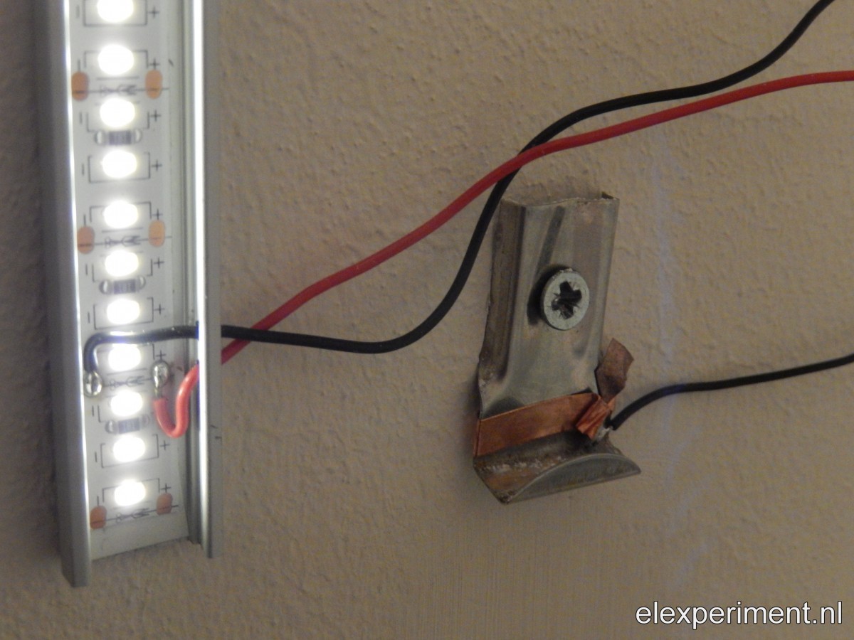
The idea is quite simple: add some LED strips next to a mirror, fitted in some nice aluminium profiles. As I don’t want full brightness in my face in the morning, brightness control is added. At first, I was thinking of using the mirror itself for some sort of capacitive control. This would allow for e.g. waving your hand in front of the mirror in some way for brightness adjustment. The mirror has however a metallic surface beneath the glass (which actually is the mirror), limiting its use as a capacitive sensor. Instead, I opted in for using the mounting clips, of which there are two at the bottom: one for up, and one for down.
Capacitive buttons
The self capacitance of these clips can be measured. In this case, the Arduino ADCTouch is used. As capacitance signals are both noisy and long term unstable, some filtering is required. The current capacitance reading is compared with a long term average. If the difference between the two is above a certain threshold, the button register touch. If the reading drops below the first threshold, minus some hysteresis (prevent triggers from noise), the button registers no touch anymore. This is somewhat similar to the Qtouch algorithm of Atmel.
boolean checkCapTouch(capSensor *c, uint8_t pin) {
  unsigned long currentTime;
  boolean driftComp = 0, recal = 0;

  currentTime = millis();

  // Every 1 second
  if (currentTime - c->lastTime > 200) {
    driftComp = 1;
    c->lastTime = currentTime;
  }

  c->signalAvg = (c->signalAvg*9)/10 + ADCTouch.read(pin, 10);
  c->signal = c->signalAvg/10;
//  c->signal = ADCTouch.read(pin, 10);

  // Initial measurement
  if (c->ref == 0 || recal) {
    uint32_t avg = 0;
    uint8_t i;
    for (i=0; i<10; i++) { avg += ADCTouch.read(pin, 10); } c->ref = avg/i;
    c->signal = c->ref;
    c->signalAvg = c->signal*10;
  }

  // If ref is smaller than signal (with a few counts margin), equalise
  if (c->signal < (c->ref - 3)) {
    c->ref = c->signal;
  }

  // Perform positive drift compensation
  if (!c->press && driftComp) {
    c->ref++;
  }

  // Calculate delta
  c->delta = c->signal - c->ref;

  // If cap touch detected, lower threshold (hysteresis)
  if (c->press && c->delta < THRESHOLD_LOW) { c->press = 0;
  } else if (!c->press && c->delta > THRESHOLD_HIGH) {
    c->press = 1;
  }

//      Serial << c->ref << "\t" << c->signal << "\t" << c->delta << "\t" << c->press << endl; return c->press;
}
The output of the capacitive touch button is then used for adjusting brightness. On a short touch, brightness is increased by a certain step. If a button is held, the brightness keeps increasing. For this purpose, I use a generalised function that allows for simple detection of multiple button states, for multiple buttons:
void checkButtonState(button *b, boolean state, boolean invert) {
  if (invert) {
    b->state = !state;
  } else {
    b->state = state;
  }

  // Reset state variables
  b->rise = 0;
  b->fall = 0;
  b->longPress = 0;
  b->longPressStart = 0;
  b->doublePress = 0;

  unsigned long currentTime = millis();

  if (b->state && !b->lastState) {        // Detect rising edge
    b->rise = 1;
    b->startTime = currentTime;
  } else if (!b->state && b->lastState) { // Detect falling edge
    b->fall = 1;
    b->releaseTime = currentTime;
  }

  if (b->state && (currentTime - b->startTime) > HOLD_TIME) {
    b->longPress = 1;
    if (b->lastLongPress == 0) {
      b->longPressStart = 1;
      b->longPressStartTime = currentTime;
    }
  }
  b->lastLongPress = b->longPress;

  if (b->rise && ((currentTime - b->releaseTime) < 300)) { b->doublePress = 1;
  }

  b->lastState = b->state;
}
Other software tricks
The human eye perceives brightness on a logarithmic scale. Because I’m a bit lazy (and because it works good enough), I use quadratic scaling of the brightness variable, which is then passed on to the PWM output. Exponential, or in this case quadratic scaling requires a very high PWM granularity, in order to have sufficient steps at low brightness. Therefore, the PWM resolution is set to 16 bits.
Besides the above mentioned software parts, not much more is happening. A final touch is to store the brightness value in EEPROM, such that at power-up the previous setting is restored. Writing to the EEPROM everytime brightness is changed would cause wear-out. Therefore, the brightness is only written to EEPROM after 5 seconds of no active user input.
Hardware
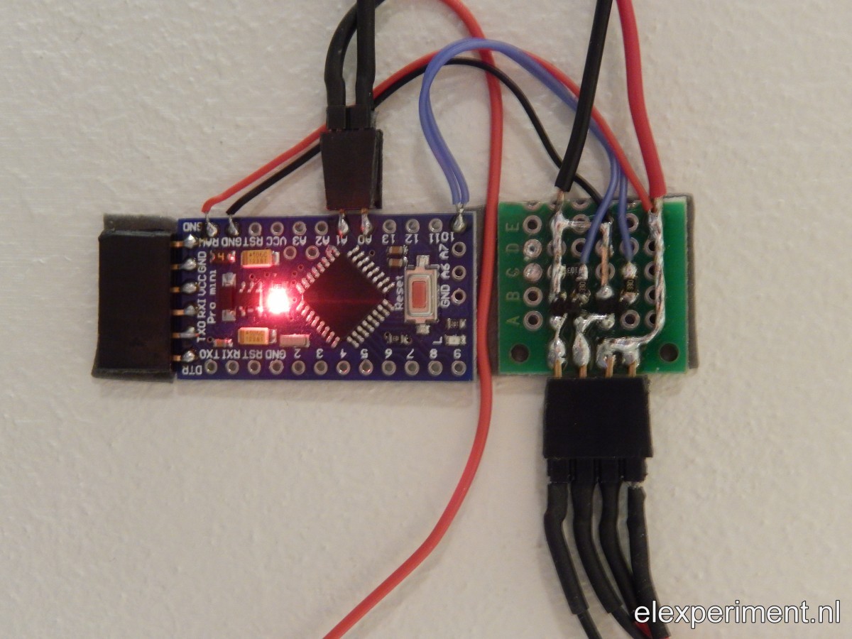
The hardware is built around an Arduino Pro Mini, running at 5V / 16MHz. The only connections are power input (12V), two touch sensors (which only require a single IO per sensor), and the PWM output. The assembly should stay flat, such that it fits behind the mirror. Therefore, two external sot-23 FETs are used, as they are compact and flat. For powering the light, I use a round 12V, 15W power supply that fits behind the mirror.
End result
During assembly, the setup looked like this:
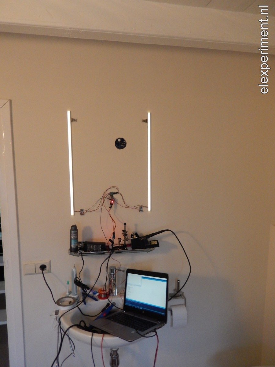
And no, I don’t have soldering equipment placed permanently in my bathroom.
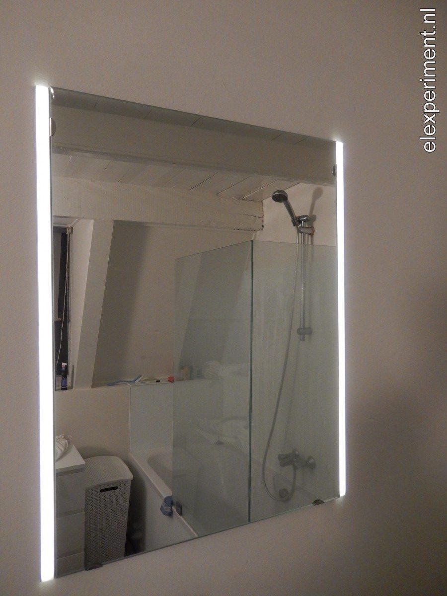
In the end, it looks very neat, leaving no traces of the electronics behind it.
An idea for a future improvement would be to store different brightness settings, that are automatically loaded for different parts of the day. This would however require an RTC, making the system a bit more complex. Another option could be to add a light sensor (e.g. LDR), and apply brightness adjustment based on background light intensity.
The Arduino source file can be found here: BathroomLight.